How to calculate total dynamic head

Finding the right pump for a water feature can be a challenge, and the stakes are high. The right pump, delivering the right flow at the right head height, while at its best efficiency range, will last and last. Specifying the wrong pump or plumbing can damage the pump, increase operating costs, shorten pump life and lead to pump failure, perhaps even a fish kill if the water feature happens to be a fish pond.
In order to properly size the pump for any water feature, you’ll need to know both components of the work it has to do, the flow and the pressure. The flow is the volume of water it can push in a given time, measured in gallons per hour (GPH). The pressure is the force required to push that flow through plumbing and up to the top of the water feature. We measure pressure in ‘feet of Head”, because it’s easy to visualize. A waterfall four feet high requires the flow be delivered at 4 feet of “Vertical Head”, plus the extra work required to push that flow through the plumbing, the “Friction Head”. The total pressure required is the “Total Dynamic Head” (TDH) of your water feature. Once you know the GPH and the TDH, you can plug them into the Comprehensive Pump Chart (Chart C) to find the right pump.
Follow the steps below to calculate TDH and find the perfect pump for your water feature.
1. Pick the look you want to achieve & the associated GPH/ft


2. Recommended flow calculation
GPH/ft (step 1) | X | Width of waterfall (ft) | = | Recommended flow (GPH) |
|---|
3. Determine friction loss from tubing
Locate the recommended flow GPH (from step 2) and the diameter of the tubing you will be using in your project to find the corresponding friction loss.
Friction loss is listed here for every foot of tubing length used in your project.
Example: For a recommended flow of 3,000 with 2" tubing, the chart shows friction loss of 0.05. In this example project, we will be using 20' of tubing, so the loss here would be 1.
Recommended Flow GPH | Tubing size | ||||||
|---|---|---|---|---|---|---|---|
0.5" | 0.75" | 1" | 1.25" | 1.5" | 2" | 3" | |
100 | 0.10 | 0.01 | |||||
200 | 0.38 | 0.05 | 0.01 | ||||
300 | 0.83 | 0.10 | 0.02 | ||||
400 | 1.00 | 0.18 | 0.04 | 0.01 | |||
500 | 2.23 | 0.27 | 0.06 | 0.02 | |||
750 | 0.50 | 0.14 | 0.04 | 0.02 | |||
1,000 | 0.84 | 0.21 | 0.07 | 0.03 | |||
1,250 | 1.20 | 0.33 | 0.10 | 0.04 | 0.01 | ||
1,500 | 0.43 | 0.15 | 0.06 | 0.02 | |||
2,000 | 0.94 | 0.26 | 0.10 | 0.03 | |||
3,000 | 2.07 | 0.52 | 0.22 | 0.05 | |||
4,000 | 1.10 | 0.43 | 0.09 | 0.01 | |||
5,000 | 1.80 | 0.67 | 0.15 | 0.02 | |||
6,000 | 0.96 | 0.22 | 0.03 | ||||
8,000 | 1.77 | 0.38 | 0.05 | ||||
10,000 | 0.59 | 0.07 | |||||
12,000 | 0.84 | 0.10 | |||||
15,000 | 0.15 | ||||||
18,000 | 0.25 | ||||||
4. Determine fitting length in feet
Located the fitting types that will be used and the fitting size. The corresponding number is the fiction loss per connection as a calculation to the equivalent if that fitting was a straight piece of tubing. For applications with multiple connections, add all corresponding values.
Example: For this project, we need one standard elbow 90°, one male to female adapter, and one swing check valve. All are 2" in diameter, so 8.5 + 4.5 + 19.0 = 32
PVC Fitting Type | Fitting size | |||||
|---|---|---|---|---|---|---|
0.5" | 1" | 1.25" | 1.5" | 2" | 3" | |
Standard Elbow 90° | 4.5 | 5.5 | 7.0 | 7.5 | 8.5 | 11.0 |
Standard Elbow 45° | 1.0 | 1.5 | 2.0 | 2.5 | 3.0 | 4.0 |
Male to Female Adapter | 1.5 | 2.0 | 3.0 | 3.5 | 4.5 | 6.5 |
Tee (used straight through) | 2.5 | 3.0 | 5.0 | 6.0 | 8.0 | 12.0 |
Tee (used through a branch) | 5.5 | 7.0 | 9.0 | 10.0 | 12.0 | 17.0 |
Swing Check Valve | 9.0 | 11.0 | 13.0 | 15.0 | 19.0 | 27.0 |
Calculate total equivalent tubing length
Fitting length (ft) (from chart above) | + | Length of tubing (ft) | = | Total equivalent tubing length (ft) |
|---|
5. Calculate friction head
Combine totals from step 3 and 4.
Friction loss | x | Total equivalent tubing length (ft) | = | Friction head (ft) |
|---|
6. Find the total dynamic head
Vertical head is the height in feet from the surface of the water the pump will be sitting in, to the highest point the water is pumped to.
Friction head (ft) | + | Vertical head (ft) | = | Total dynamic head |
|---|
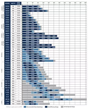
7. Choose you pump
Find the total dynamic head at the top of this chart, then find the pumps below that provide at least that recommended flow. Grey colored cells indicate that the total dynamic head is outside the pump’s operating range and the pump will likely not last in this application. The light blue cells indicate the pump is operating within its operating range. Dark blue means the total dynamic head is in the pump’s best efficiency range, where the pump will run best and longest. If the chart gives you a choice of more than one pump, check for the type that best fits your application from the list below, then check for the lowest wattage, to save on operating costs.
For low head, low volume applications, use magnetic drive pumps (MD Series)
For low head, very high volume applications, use axial pumps (L-Series) with 3″ or larger tubing
For medium head, medium volume, use asynchronous pumps (TT-Series)
For high head, high volume applications, use direct drive pumps (A-Series)
For solids and dirty water applications, use direct drive solids handling pumps (PAF and SH-Series)